Stáhnout prezentaci
Prezentace se nahrává, počkejte prosím

1
Bi9393 Analytická cytometrie Lekce 3
Karel Souček, Ph.D. Oddělení cytokinetiky Biofyzikální ústav AV ČR, v.v.i. Královopolská 135 Brno tel.: K. Souček Bi9393 Analytická cytometrie

16
Particle Delivery: Hydrodynamic Focusing
Conventional Instrumentation: Low Flow Rates (12µL/min) Hydrodynamic core Narrow particle focus = Narrow distribution Laser Cross Sectional Area Count Intensity Sample core is ‘pinched’ by fast flowing sheath Sample volume ratios of 100 – 1000 Large ratios => low sample inputs Resolution of particle populations To really understand what is different and unique about acoustic focusing, one first needs to understand the current most commonly used method for focusing, called hydrodynamic focusing. In this method, the sample is injected into a stream of sheath fluid where it is completely surrounded by sheath, the sample core is then centered in the sheath fluid where the laser beam will then interact with the particles. Based on principles relating to laminar flow, the sample core remains separate but coaxial within the sheath fluid. The flow of sheath fluid accelerates the particles and restricts them to the center of the sample core. This process is known as hydrodynamic focusing. Where the sample core is narrow, the particles interact with the laser beam optimally and a narrow distribution results as seen in the histogram above. sheath sheath
 Hydrodynamic core. Narrow particle focus = Narrow distribution. Laser Cross Sectional Area. Count. Intensity. Sample core is ‘pinched’ by fast flowing sheath. Sample volume ratios of 100 – Large ratios => low sample inputs. Resolution of particle populations. To really understand what is different and unique about acoustic focusing, one first needs to understand the current most commonly used method for focusing, called hydrodynamic focusing. In this method, the sample is injected into a stream of sheath fluid where it is completely surrounded by sheath, the sample core is then centered in the sheath fluid where the laser beam will then interact with the particles. Based on principles relating to laminar flow, the sample core remains separate but coaxial within the sheath fluid. The flow of sheath fluid accelerates the particles and restricts them to the center of the sample core. This process is known as hydrodynamic focusing. Where the sample core is narrow, the particles interact with the laser beam optimally and a narrow distribution results as seen in the histogram above. sheath. sheath.")
17
Particle Delivery: Hydrodynamic Focusing
Conventional Instrumentation: High Flow Rate (60µL/min) Hydrodynamic core Intensity Count Broad particle focus = Broad distribution Laser Cross Sectional Area Increased sample input = increase core size Particle distributions broadened, CVs increase Instrument resolution decreased Historically, low volumetric sample rates used (25 ml/min – 150 ml/min) sheath sheath
 Hydrodynamic core. Intensity. Count. Broad particle focus = Broad distribution. Laser Cross Sectional Area. Increased sample input = increase core size. Particle distributions broadened, CVs increase. Instrument resolution decreased. Historically, low volumetric sample rates used (25 ml/min – 150 ml/min) sheath. sheath.")
18
Attune® Acoustic Focusing Cytometer

19
Acoustic Focusing = Better Precision
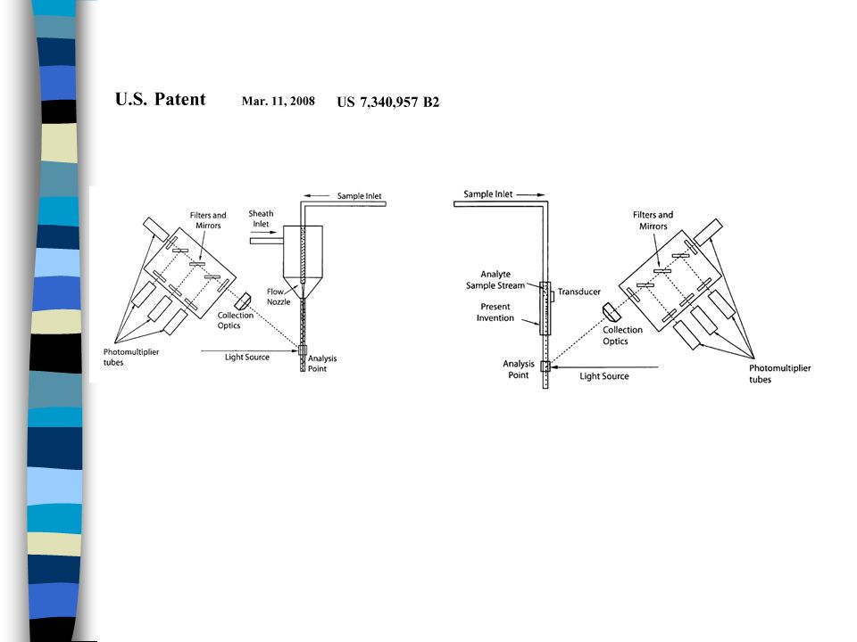
12 µL/min Narrow particle focus = Narrow distribution 1000 µL/min sheath sheath Acoustic focusing of particles occurs prior to mixing with sheath fluid sheath sheath Fundamentals of acoustic focusing in flow cytometry: Picture in the middle is a comparison of a manifold taken from a traditional hydrodynamic focusing cytometer (left) compared to a manifold taken from the Attune Cytometer and represented “in action” by the cartoons directly to the left and right of the photograph. The picture on the far right shows a full acoustic device as well as the manifold at the top. Here, regardless of the sample volume that is moved through the flow cell, cells are focused by the acoustic device prior to entering the manifold and, ultimately, the flow cell. So, at low sample volumes (left) and high sample volumes (right), focus is maintained. This also means that very little sheath is needed. It is only used to allow for varying the amount of sample while maintaining the correct flow rate; and, is used to prevent reagent from staining the inside of the cuvette. Acoustic focusing Module
 compared to a manifold taken from the Attune Cytometer and represented in action by the cartoons directly to the left and right of the photograph. The picture on the far right shows a full acoustic device as well as the manifold at the top. Here, regardless of the sample volume that is moved through the flow cell, cells are focused by the acoustic device prior to entering the manifold and, ultimately, the flow cell. So, at low sample volumes (left) and high sample volumes (right), focus is maintained. This also means that very little sheath is needed. It is only used to allow for varying the amount of sample while maintaining the correct flow rate; and, is used to prevent reagent from staining the inside of the cuvette. Acoustic focusing Module.")
23
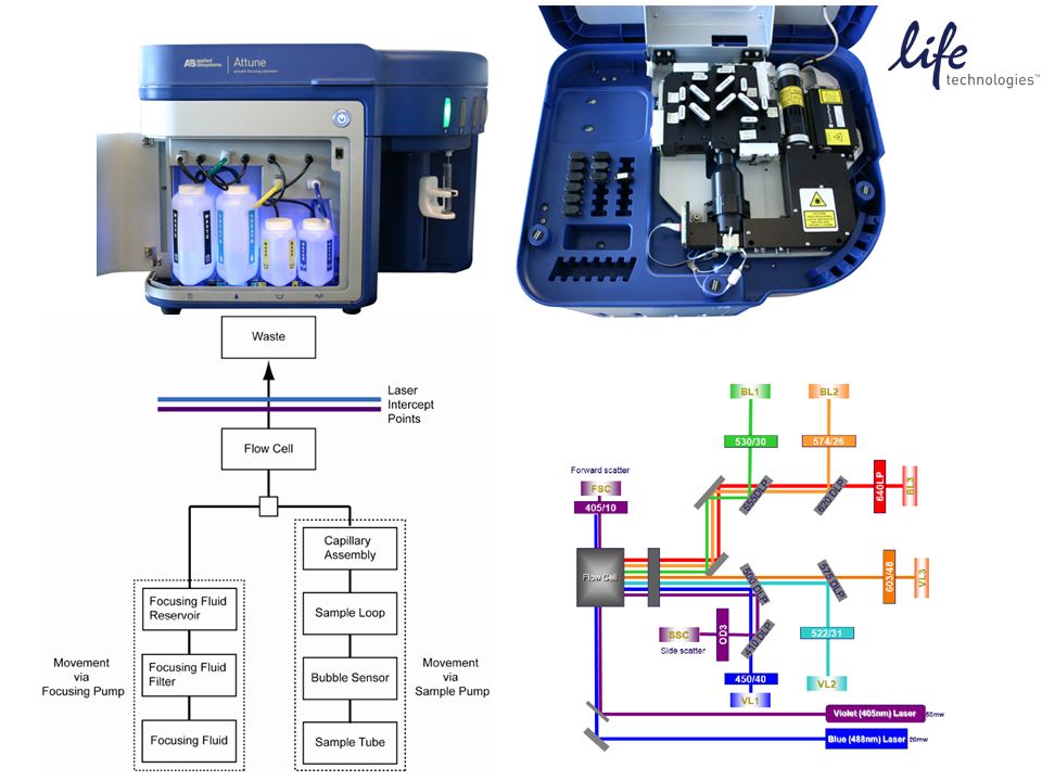
Attune (2 lasers, 6 detectors setup)
fluorochrome 405 VL1 450/50 Pacific Blue, Alexa Fluor 405, Brilliant Violet 421 VL2 522/31 Horizon V500, LIVE/DEAD Aqua VL3 603/48 LIVE/DEAD Yellow, Qdot 605 488 BL1 530/30 FITC, GFP, Alexa Fluor 488, Calcein, LIVE/DEAD Green, ALDEFLUOR, HiLyte 488 BL2 574/26 PE, propidium iodide, Hilyte 555 BL3 640 LP PerCP, Pe-Cy7, PerCP-eFluor 710, LIVE/DEAD Red, 7-AAD

24
Attune - Key performance features include:
Breakthrough acoustic technology that focuses cells or particles Highest sample delivery rates commercially available (up to 1,000 μL/minute) User-selectable collection rates Equipped with: Blue/Violet: 488 nm (20 mW) and 405 nm (50 mW) lasers 8 parameters—6-color detection plus side scatter and forward scatter User-changeable bandpass and dichroic filters Simplified fluorescence compensation Manual and automated compensation Adjustable PMT voltage settings Detection of up to 20,000 events/sec and 20 million events/file Calibrated delivery volumes for volumetric analysis and absolute cell counts Electronic resolution of 6 decades Low fluid consumption (about 1 L/day); self-contained fluids Countertop instrument—fits on standard lab bench or in laminar Software: No software licensing fees Output file format: FCS 3.0 Live gating with automatic saving User and administrator log-in
 User-selectable collection rates. Equipped with: Blue/Violet: 488 nm (20 mW) and 405 nm (50 mW) lasers. 8 parameters—6-color detection plus side scatter and forward scatter. User-changeable bandpass and dichroic filters. Simplified fluorescence compensation. Manual and automated compensation. Adjustable PMT voltage settings. Detection of up to 20,000 events/sec and 20 million events/file. Calibrated delivery volumes for volumetric analysis and absolute cell counts. Electronic resolution of 6 decades. Low fluid consumption (about 1 L/day); self-contained fluids. Countertop instrument—fits on standard lab bench or in laminar. Software: No software licensing fees. Output file format: FCS 3.0. Live gating with automatic saving. User and administrator log-in.")
25
Cancer The Attune® Acoustic Focusing Cytometer, with its fast acquisition times and increased precision, overcomes the technological hurdles involved in analyzing CECs. Stem Cells Side Population Analysis In this study, we demonstrate the ability of the Attune® Acoustic Focusing Cytometer with the blue/ violet laser configuration to quickly analyze a large number of events in search of very rare populations of stem cells. Human Mesenchymal Stem Cells (hMSCs) Adult human mesenchymal stem cells (hMSCs) are rare fibroblast-like cells capable of differentiating into a variety of cell tissues, including bone, cartilage, muscle, ligament, tendon, and adipose. Cell Cycle Analysis Cell cycle analysis is just one example of an application in which precise detection of differences in fluorescence intensity between multiple cell populations is critical... Cell Proliferation Successful proliferation analysis by dye dilution requires sensitive instrumentation and an extremely bright dye to accurately distinguish fluorescently labeled cells from autofluorescence after several cell divisions... Marine Sample Analysis Flow cytometry is a powerful tool for studying the biology, ecology, and biogeochemistry of marine photosynthetic picoplankton... Immunophenotyping The Attune® Acoustic Focusing Cytometer exhibits excellent segregation of populations in immunophenotyping experiments (with up to 6 colors)... Apoptosis The Attune® Acoustic Focusing Cytometer is compatible with a broad offering of reagents and kits for flow cytometric apoptosis testing... GFP & RFP Detection Data for GRP and RFP detection were collected from the Attune® Acoustic Focusing Cytometer using human osteosarcoma cells (U2OS) and BacMam CellLight® reagents... Microbiological Applications In recent years the application of flow cytometry to the study of various microbiological phenomena has increased, finding utility in studies that include detection and quantification...
 Adult human mesenchymal stem cells (hMSCs) are rare fibroblast-like cells capable of differentiating into a variety of cell tissues, including bone, cartilage, muscle, ligament, tendon, and adipose. Cell Cycle Analysis. Cell cycle analysis is just one example of an application in which precise detection of differences in fluorescence intensity between multiple cell populations is critical... Cell Proliferation. Successful proliferation analysis by dye dilution requires sensitive instrumentation and an extremely bright dye to accurately distinguish fluorescently labeled cells from autofluorescence after several cell divisions... Marine Sample Analysis. Flow cytometry is a powerful tool for studying the biology, ecology, and biogeochemistry of marine photosynthetic picoplankton... Immunophenotyping. The Attune® Acoustic Focusing Cytometer exhibits excellent segregation of populations in immunophenotyping experiments (with up to 6 colors)... Apoptosis. The Attune® Acoustic Focusing Cytometer is compatible with a broad offering of reagents and kits for flow cytometric apoptosis testing... GFP & RFP Detection. Data for GRP and RFP detection were collected from the Attune® Acoustic Focusing Cytometer using human osteosarcoma cells (U2OS) and BacMam CellLight® reagents... Microbiological Applications. In recent years the application of flow cytometry to the study of various microbiological phenomena has increased, finding utility in studies that include detection and quantification...")
26
Example: Detecting human circulating endothelial cells
using the Attune® Acoustic Focusing Cytometer Circulating endothelial cells (CECs) are mature cells shed from blood vessel walls during the natural process of endothelial cell turnover. Elevated levels of CECs have been reported in a host of pathological conditions including cardiovascular disorders, infectious diseases, immune disorders, post transplantation analysis, and cancer. CECs are reported to be present in very low numbers: 0.01%–0.0001% of all peripheral blood mononuclear cells
 are mature cells shed from blood vessel. walls during the natural process of endothelial cell turnover. Elevated levels of CECs have been reported in a host of pathological conditions including cardiovascular disorders, infectious diseases, immune disorders, post transplantation analysis, and cancer. CECs are reported to be present in very low numbers: 0.01%–0.0001% of all peripheral blood mononuclear cells.")
27
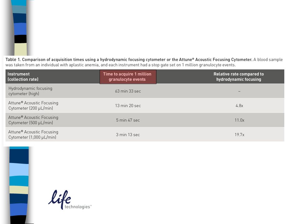
Attune® Throughput Compared to Hydrodynamic Focused Instruments
Maximum Sample Input Rate (ml/min) 100 200 300 400 500 600 700 800 900 1000 Instrument 1 Instrument 2 Instrument 6 Instrument 5 Instrument 4 Instrument 3 Attune® Hydrodynamic Focused Instruments With Precious and Rare samples, the problem is that certain cells may not have enough volume of the original sample or cells may be fragile and can not withstand the centrifugation required to concentrate enough to run at low sample input rates. With the Attune® cytometer, being able to increase the sample rate up to 10x that of a traditional flow cytometer enables these customers to run rare or dilute samples. Also, because you can dilute your sample prior to running it on the Attune, customers with limited sample can save some of their sample for other analyses i.e. PCR, western, imaging etc. Attune® can analyze at sample rates from 25µL/min to 1000µL/min without losing accuracy Traditional Flow Cytometers can only run at most 150µL/min and will sacrifice data quality Higher sample rates enable dilution of limited samples and analysis of Rare Events Faster
 Instrument 1. Instrument 2. Instrument 6. Instrument 5. Instrument 4. Instrument 3. Attune® Hydrodynamic Focused Instruments. With Precious and Rare samples, the problem is that certain cells may not have enough volume of the original sample or cells may be fragile and can not withstand the centrifugation required to concentrate enough to run at low sample input rates. With the Attune® cytometer, being able to increase the sample rate up to 10x that of a traditional flow cytometer enables these customers to run rare or dilute samples. Also, because you can dilute your sample prior to running it on the Attune, customers with limited sample can save some of their sample for other analyses i.e. PCR, western, imaging etc. Attune® can analyze at sample rates from 25µL/min to 1000µL/min without losing accuracy. Traditional Flow Cytometers can only run at most 150µL/min and will sacrifice data quality. Higher sample rates enable dilution of limited samples and analysis of Rare Events Faster.")
29
Attune souhrn Výhody: rychlost měření jednoduché ovládání sw licence bez omezení snadná výměna emisních filtrů nízká spotřeba nosné kapaliny (cca 1L denně) Limitace: jen dva lasery (6 barev) pouze originální roztoky dlouhý (i když automatický) shutdown sw nedokáže importovat FCS data nutnost nastavit určitý akviziční objem vzorku
 Limitace: jen dva lasery (6 barev) pouze originální roztoky. dlouhý (i když automatický) shutdown. sw nedokáže importovat FCS data. nutnost nastavit určitý akviziční objem vzorku.")
31
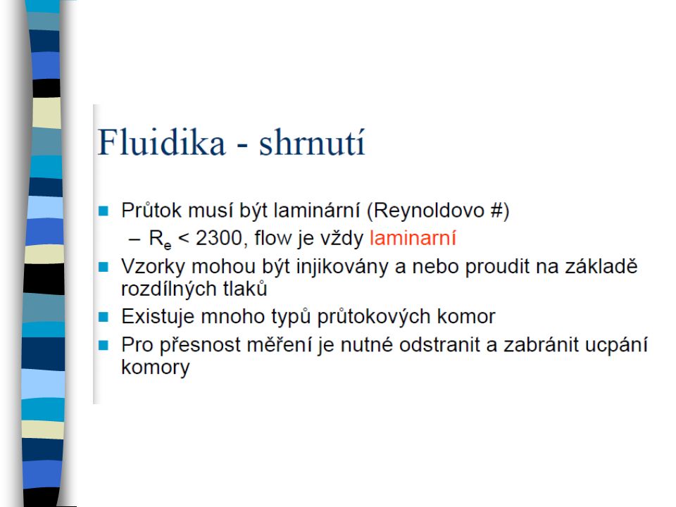
Fluidika – shrnutí 2 tlak nosné (oplašťující) kapaliny vede pufr kyvetou a vyšší tlak ve zkumavce se vzorkem zavádí vzorek do kyvety. Princip hydrodynamického zaostření zarovná buňky v kyvetě „jako perly na šňůrce“ předtím než dojdou do bodu kde protnout paprsek laseru. Hydrodynamické zaostření nemůže oddělit buněčné agregáty. Průtoková cytometrie vyžaduje suspenzi jednotlivých buněk!

32
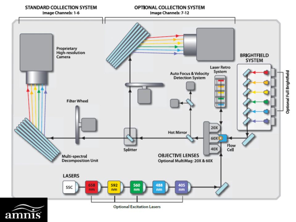
Image Stream & Flowsight Amnis – kombinace průtokové cytometrie a analýzy obrazu

34
Amnis - aplikace

35
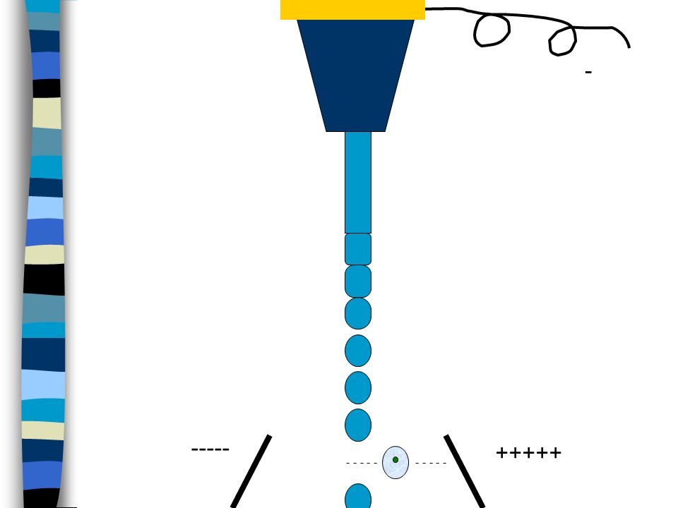
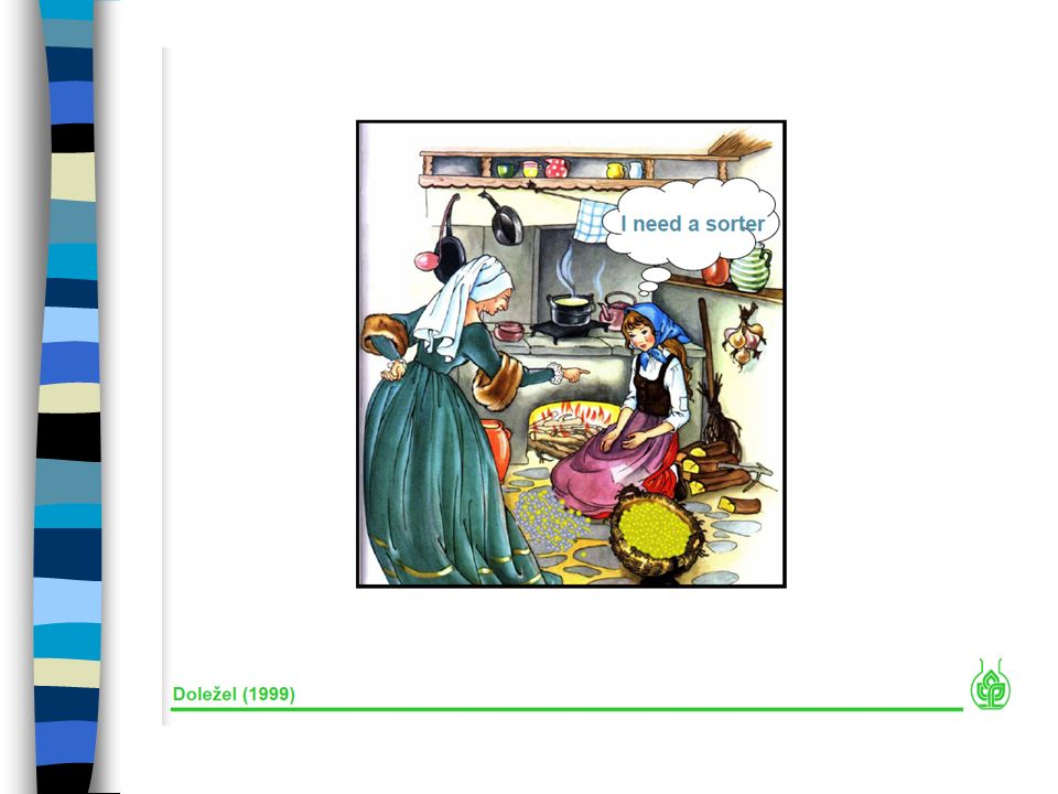
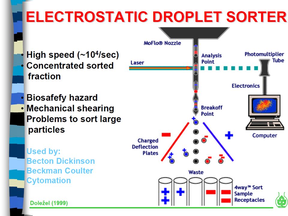
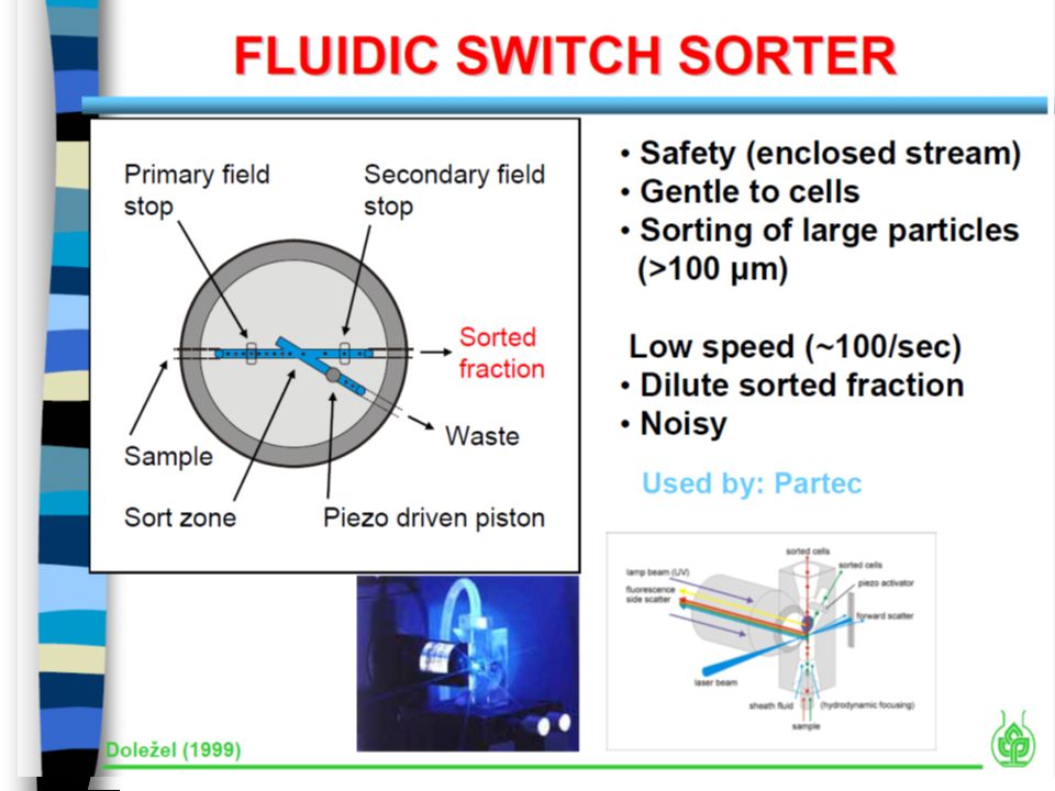
Principy průtokové cytometrie a sortrování
sorting zpracování signálu analýza dat kompenzace signálu K. Souček Bi9393 Analytická cytometrie

38
----- +++++
39
----- +++++

40
----- +++++

41
+++++ +++++ ----- +++++
42
++ ++ +++++ +++++ ----- +++++
43
+ + +++++ +++++ ----- +++++
44
----- +++++ +++++ ----- +++++

45
----- ----- ----- +++++ +++++ +++++
46
- - - - ----- +++++
47
- - ----- +++++
48
- ----- +++++
49
- ----- +++++

50
- ----- +++++
51
http://www. cyto. purdue
54
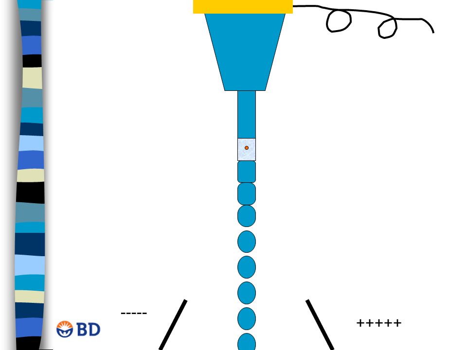
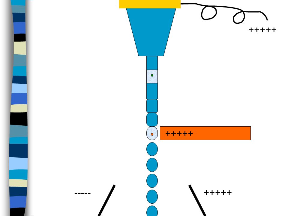
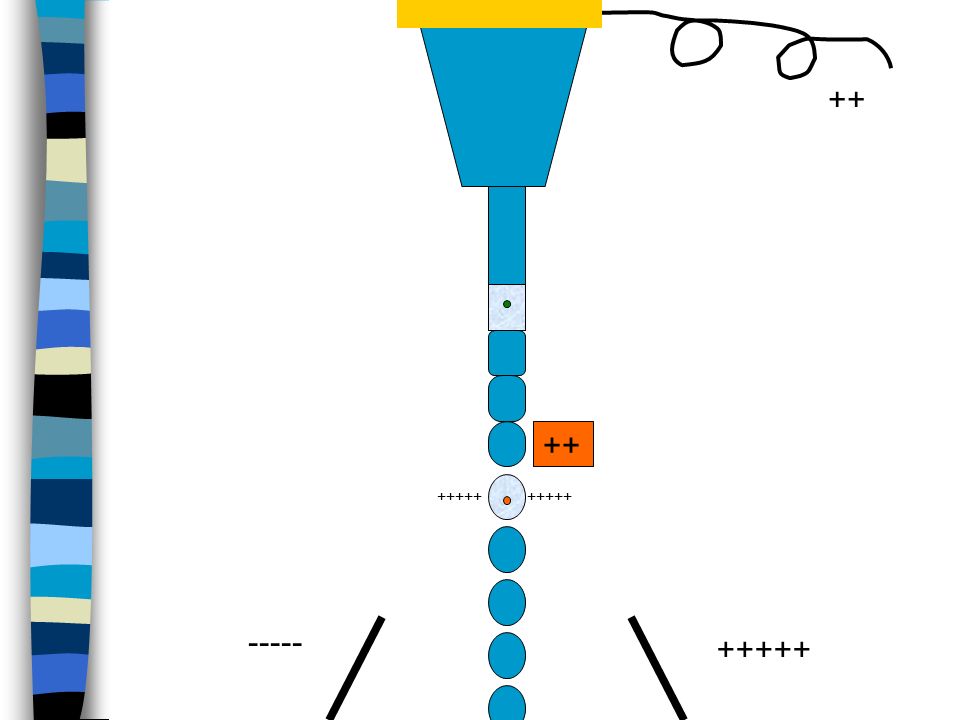
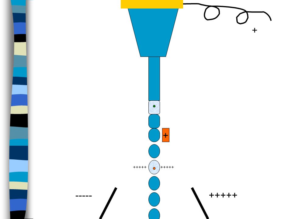
SORTING

55
SORTING Frequency Charge Drop Delay Amplitude

56
SORTING Sheath Pressure Nozzle Size Frequency Amplitude

57
SORTING Drop delay Interrogation point Breakoff

58
SORTING Each sort setup includes: Sheath pressure
Breakoff window values Side Stream window values Instrument window > Laser tab values

59
SORTING - Streams Good Bad

60
SORTING – Setup Side Streams

61
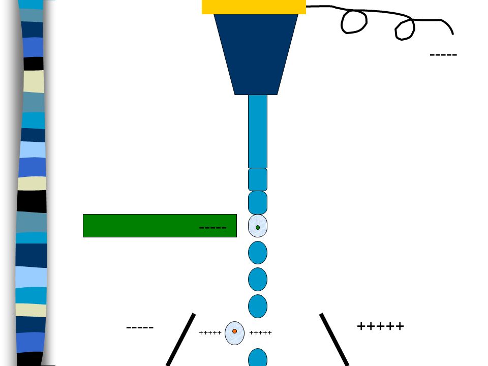
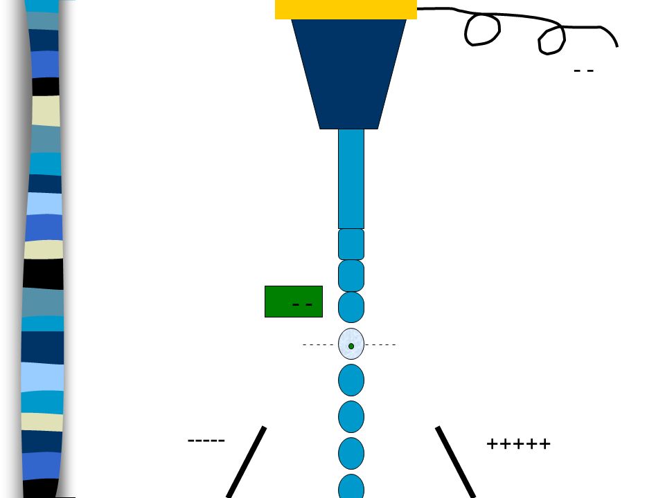
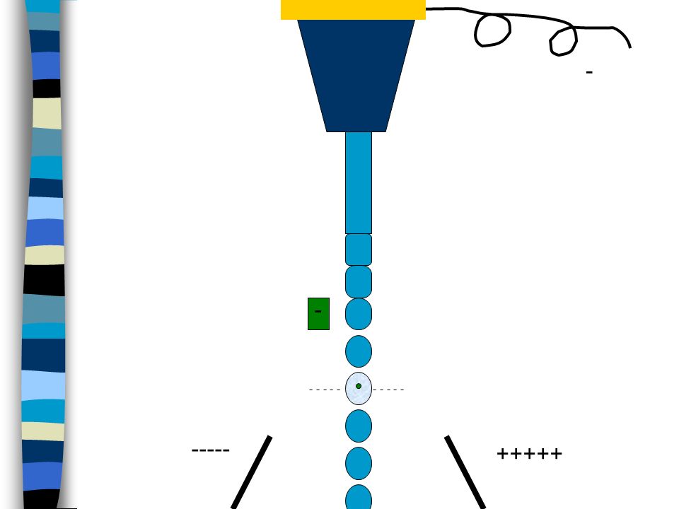
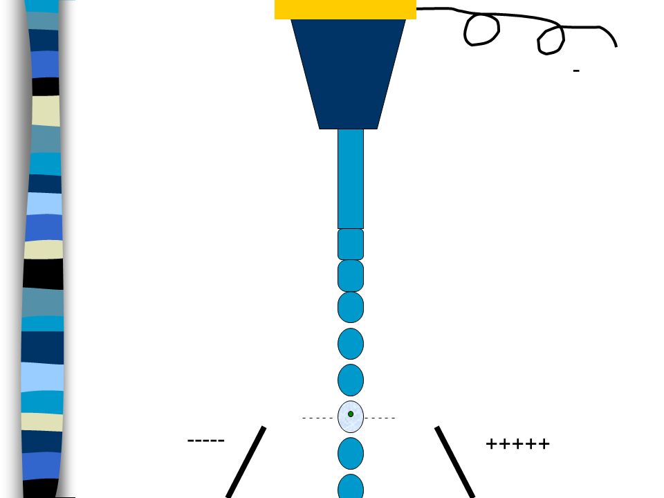
Drop Delay BD FACS™ Accudrop technology Accudrop beads Diode laser
interrogation point drop delay breakoff Waste BD FACS™ Accudrop technology Accudrop beads Diode laser Camera Optical filter Before sorting, you need to make sure that you have an accurate drop delay setting. The Aria has integrated Accudrop technology which provides a simple way to adjust the drop delay. The components used for Accudrop: Diode laser: A low-power red laser which illuminates the lower portion of the stream when the sort block door is closed (there’s a safety interlock). Camera: Provides an image of the side streams visible in this window. (located behind the round window in the sort block) Optical filter: Used for viewing the fluorescence from the droplets containing Accudrop beads. (point out the button on this image that moves the filter into place) Accudrop beads: Beads that are excited by the diode laser and emit within the range of the optical filter. The drop delay is the distance between the laser intercept and the last connected drop, measured in time. The system needs to know when to charge the stream so that the intended droplet is charged before it is detached from the stream. This diagram shows the diode laser and the lower camera window. When setting the drop delay, the waste aspirator drawer is blocking the collection tubes, so all beads will go to waste. Essentially, Accudrop allows us to view the accuracy of our sort in real-time, without having to do a post-sort analysis.
. Camera: Provides an image of the side streams visible in this window. (located behind the round window in the sort block) Optical filter: Used for viewing the fluorescence from the droplets containing Accudrop beads. (point out the button on this image that moves the filter into place) Accudrop beads: Beads that are excited by the diode laser and emit within the range of the optical filter. The drop delay is the distance between the laser intercept and the last connected drop, measured in time. The system needs to know when to charge the stream so that the intended droplet is charged before it is detached from the stream. This diagram shows the diode laser and the lower camera window. When setting the drop delay, the waste aspirator drawer is blocking the collection tubes, so all beads will go to waste. Essentially, Accudrop allows us to view the accuracy of our sort in real-time, without having to do a post-sort analysis.")
62
Sorting - Sort Masks Cells are randomized distributed over the stream

63
Sorting - Sort Masks Trailing Interrogated Leading

64
Mask A region of the stream monitored for the presence of cells
Determines how drops will be deflected if a sorting conflict occurs Measured in 1/32 drop increments At the laser intercept particles are defined as wanted or not based on the gates you created in the software. However, while the particle is traveling down the stream another decision is made on whether or not the particle will be sorted based upon the Sort Precision mode. A sort precision mode is made up of a combination of masks. A mask is a region of the stream that will be considered to make a decision if there’s a sorting conflict. Each mask is measured in 1/32 drop increments. The next few slides will discuss each individual mask, then we’ll look at how those three masks are combined into precision modes. Note to instructor: Encourage customers to hold questions about putting the masks together until after you’ve discuss the basic definitions of all three. 4 8 16 4 8 16 Mask = 0 Mask = 8 Mask = 16 Mask = 32

65
Conflict Resolution Precision modes include three types of masks Yield
Purity Phase At the laser intercept particles are defined as wanted or not based on the gates you created in the software. However, while the particle is traveling down the stream another decision is made on whether or not the particle will be sorted based upon the Sort Precision mode. A sort precision mode is made up of a combination of masks. A mask is a region of the stream that will be considered to make a decision if there’s a sorting conflict. Each mask is measured in 1/32 drop increments. The next few slides will discuss each individual mask, then we’ll look at how those three masks are combined into precision modes. Note to instructor: Encourage customers to hold questions about putting the masks together until after you’ve discuss the basic definitions of all three.

66
Target particles in a drop with 1/32-drop resolution
Sorting - Sort Masks Sort decisions are determined by sort masks Target particles in a drop with 1/32-drop resolution

67
Sorting - Yield Mask The yield mask defines how many drops will be sorted Yield mask of 8/32 indicated in blue; target particle shown in green Yield Mask

68
Sorting - Purity Mask Purity mask of 8/32 in blue, 4/32 in each adjacent drop; target particles in green, non-target particles in red Purity Mask Purity Mask

71
Creation of a Voltage Pulse
Laser 1 Voltage Time 2 Laser Voltage Time Voltage 3 Laser Time

72
Height, Area, and Width Pulse area(A) Voltage Time (µs)
Pulse Height (H) Pulse Width (W)
 Pulse Width (W)")
73
analog signal intesity
Signal processing FL-1 (H) FL-2 (H) dot plot 1000 Zesílení signálu (!) lin nebo log Analog/digital conversion time analog signal intesity VOLTAGE FSC ~ cell size Height Width Area ( ∫ ) FL- (H, W, A) FL-1 (530/30nm) ~ green fluo. FL-2 (585/42nm) ~ red fluo. K. Souček Bi9393 Analytická cytometrie
 FL-2 (H) dot plot Zesílení signálu (!) lin nebo log. Analog/digital. conversion. time. analog signal intesity. VOLTAGE. FSC ~ cell size. Height. Width. Area ( ∫ ) FL- (H, W, A) FL-1 (530/30nm) ~ green fluo. FL-2 (585/42nm) ~ red fluo. K. Souček Bi9393 Analytická cytometrie.")
74
Analog to Digital Converter
16, 364 12420 7650 1985 340 baseline Time

75
Analog to Digital Converter
Conversion Signal Out Digital data to memory Photon In Voltage In PMT Power Supply Sample the pulse 10 MHz Digitize the pulse 16,384 levels Levels 0–1000 Volts

76
Parameters Area: Sum of all height values
14524 9568 10270 4004 3060 358 282 Area: Sum of all height values Height: Maximum digitized value X 16 Width: Area/Height X 64K Data is displayed on 262,144 scale

80
24=16

81
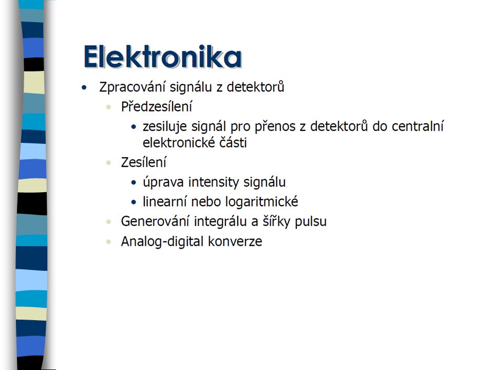
Lineární a logaritmický obvod
kompenzace fluorescenčního signálu

82
AD převodníky 28 = 256 210 = 1024 . Počet bitů # kanálů rozlišení 8
39.1 mV 10 1024 9.77 mV 12 4096 2.44 mV 14 16384 610 mV 16 65536 153 mV 18 262144 38.1 mV 20 9.54 mV 22 2.38 mV 24 596 nV Full scale measurement range = 0 to 10 volts ADC resolution is 12 bits: 212 = 4096 quantization levels ADC voltage resolution is: (10-0)/4096 = volts = 2.44 mV K. Souček Bi9393 Analytická cytometrie
/4096 = volts = 2.44 mV. K. Souček Bi9393 Analytická cytometrie.")
83
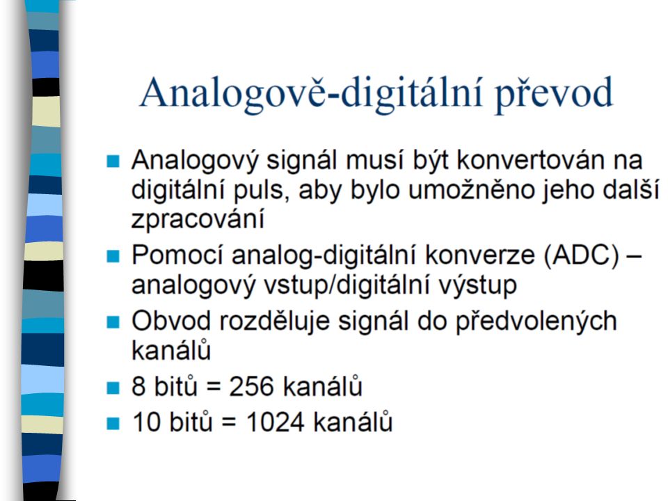
Kolik bitů? Pokud konvertujeme analogový signál pomocí 8 bitového ADC – máme 256 kanálů (28=256) odpovídajících rozsahu 0-10 V Rozdíl mezi kanály je 10/256=~40mV 10V 1V 100mV Channels upraveno podle J.P.Robinson

84
Ideální logaritmický zesilovač
10 V 1 V 100 mV 1 mV Channels Linearní Log 10 mV Log amp upraveno podle J.P.Robinson

85
Logaritmické zesílení & dynamický rozsah
lin log upraveno podle J.P.Robinson

86
Kompenzace fluorescenčního signálu
…později

87
Analýza dat Zobrazení dat Gating histogram dot plot isometric display
contour plot chromatic (color) plots 3 D projection Gating
 plots. 3 D projection. Gating.")
88
Způsoby pro zobrazení dat
K. Souček Bi9393 Analytická cytometrie

89
Histogram distribuce četnosti
Histogram zobrazuje četnost částic pro jeden parametr Jednoduchý výstup Nekorelujeme s dalším parametrem Problém s identifikací populací K. Souček Bi9393 Analytická cytometrie

90
Dot plot Zobrazuje korelaci dvou libovolných parametrů
Jednotlivé tečky představují konkrétní změřené buňky (částice) Hodnoty pro řadu částic mohou ležet ve stejném místě Nemáme informaci o relativní denzitě částic Problémy s vykreslením v případě velkých objemů dat K. Souček Bi9393 Analytická cytometrie
 Hodnoty pro řadu částic mohou ležet ve stejném místě. Nemáme informaci o relativní denzitě částic. Problémy s vykreslením v případě velkých objemů dat. K. Souček Bi9393 Analytická cytometrie.")
91
Density & contour plot Density plot:
Zobrazuje dva parametry jako frekvenci četnosti barva a nebo její odstín odpovídá četnosti částic Contour plot: spojnice spojuje body (částice) se stejnou hodnotou signálu V podstatě simulujeme 3D graf – třetí rozměr je frekvence K. Souček Bi9393 Analytická cytometrie
 se stejnou hodnotou signálu. V podstatě simulujeme 3D graf – třetí rozměr je frekvence. K. Souček Bi9393 Analytická cytometrie.")
92
Čas jako jeden z parametrů
K. Souček Bi9393 Analytická cytometrie

93
3D zobrazení 2 parametry + četnost 3 parametry společně
K. Souček Bi9393 Analytická cytometrie

94
3 Color Combinations APC PE FITC Positives Negatives 4+4+4=12 4+4=8
upraveno podle J.P.Robinson

95
3 Color Combinations APC PE FITC 4+4+4=12 upraveno podle J.P.Robinson
PE-FITC Pattern FITC TR-FITC Pattern TR-PE Pattern Phycoerytherin .1 1 10 100 1000 CD4 CD5 CD38 K/L CD45 CD3 Negative CD10 HLA-DR CD20 CD8 CD7 CD2 CD8 (dim) K Texas Red IgM IgG L 4+4+4=12 APC PE FITC upraveno podle J.P.Robinson
 K. Texas Red. IgM. IgG. L =12. APC. PE. FITC. upraveno podle J.P.Robinson.")
96
„Gating“ Real-time gating vs. softwarový „gating“ Určení regionů
Strategie „gatingu“ Analýza kvadrantů Boolean „gating“ zpětný „gating“

97
Real-Time vs. Software Gating
Real-time (live) gating: -omezuje akceptovaná data během měření Software (analysis) gating: -vyřazuje určitá data během následné analýzy upraveno podle J.P.Robinson
 gating: -omezuje akceptovaná data během měření. Software (analysis) gating: -vyřazuje určitá data během následné analýzy. upraveno podle J.P.Robinson.")
98
Určení regionů Objektivní nebo subjektivní?
-školení/schopnosti/trénink Možné tvary: -obdelník -elipsa -“free-hand“ (polygon) -kvadrant Statistika - počet - podíl (%) - průměr, medián, S.D., CV, ….
 -kvadrant. Statistika. - počet. - podíl (%) - průměr, medián, S.D., CV, ….")
99
Region vs. gate Region oblast (plocha) v grafu definovaná uživatelem
mnoho regionů v jednou grafu ohraničujeme pomocí nich populace našeho zájmu je možné je barevně odlišit je definován stejně pro všechny vzorky v analýze Gate je definován jako jeden a nebo více regionů zkombinovaných pomocí logických operátorů (AND, OR, NOT; Booleova logika) K. Souček Bi9393 Analytická cytometrie
 K. Souček Bi9393 Analytická cytometrie.")
100
Using Gates Region 1 established Gated on Region 1 log PE
upraveno podle J.P.Robinson

101
Statistika Aritmerický průměr Geometrický průměr Medián
– odhad střední hodnoty – není ovlivněn extrémními hodnotami Směrodatná odchylka Koeficient variance Modus – nejčastější hodnota K. Souček Bi9393 Analytická cytometrie

102
Statistika pro histogram
K. Souček Bi9393 Analytická cytometrie

103
Analýza kvadrantů (+ -) (+ +) ( - +) (- -)
K. Souček Bi9393 Analytická cytometrie

104
Logický „Gating“ (Booleova logika)
S překrývajícími se oblastmi máme mnoho možností: upraveno podle J.P.Robinson

105
Boolean Gating Not Region 1: upraveno podle J.P.Robinson

106
Boolean Gating Not Region 2: upraveno podle J.P.Robinson

107
Boolean Gating Region 1 or Region 2: upraveno podle J.P.Robinson

108
Boolean Gating Region 1 and Region 2: upraveno podle J.P.Robinson

109
Boolean Gating Not (Region1 and Region 2): upraveno podle J.P.Robinson
: upraveno podle J.P.Robinson")
110
Light Scatter Gating Side Scatter Projection Neutrophils Scale
1000 200 100 50 40 Monocytes 30 20 15 Lymphocytes 8 200 400 600 800 1000 90 Degree Scatter upraveno podle J.P.Robinson

111
Back Gating Region 4 established Back-gating using Region 4 Back gate
log PE Region 4 established Back-gating using Region 4 upraveno podle J.P.Robinson

112
Back Gating K. Souček Bi9393 Analytická cytometrie

113
3 Parameter Data Display
FITC+ APC+ PE + APC+ FITC+ PE+ upraveno podle J.P.Robinson

114
Vícebarevné analýzy generují mnoho dat…
5 color 4 color 3 color Log Fluorescence QUADSTATS ++ -- +- -+ upraveno podle J.P.Robinson

116
Detection and monitoring of normal and leukemic cell populations with hierarchical clustering of flow cytometry data HCA‐Main hematopoietic populations in normal BM. A: Dendrogram with heatmap‐HCA of 104 ungated events acquired from normal BM. Heatmap shows relative levels of all eight parameters (columns) in all 104 events (rows) in color coding (blue, low expression; red, high expression). Dendrogram shows the hierarchy of cells based on their similarity in all parameters measured. The x‐axis under the dendrogram represents similarity distance. Colored branches of the dendrogram are selected clusters, as displayed in B. B: The main populations (as identified by HCA) are displayed on a conventional forward versus side scatter dot plot. C: All two‐parameter combination plots of a defined cluster (marked by red rectangle in A). This population is negative for most of the antibodies from the B cell panel and may be difficult to detect by standard gating as it overlaps with other populations in all 28 two‐parameter plots. Nevertheless it is a compact, homogenous population most likely of T cell origin. This red population was drawn on top of the remaining cells (gray). D: Mirror image to C. The gray population was drawn on top of the red population. Fluorescent dyes used were: CD10‐FITC, CD22‐PE, CD117‐PerCP‐Cy5.5, CD38‐PE‐Cy7, CD34‐APC, CD19‐APC‐Cy7, and in all cases pulse height was used. © This slide is made available for non-commercial use only. Please note that permission may be required for re-use of images in which the copyright is owned by a third party. Cytometry Part A Volume 81A, Issue 1, pages 25-34, 11 OCT 2011 DOI: /cyto.a
 in all 104 events (rows) in color coding (blue, low expression; red, high expression). Dendrogram shows the hierarchy of cells based on their similarity in all parameters measured. The x‐axis under the dendrogram represents similarity distance. Colored branches of the dendrogram are selected clusters, as displayed in B. B: The main populations (as identified by HCA) are displayed on a conventional forward versus side scatter dot plot. C: All two‐parameter combination plots of a defined cluster (marked by red rectangle in A). This population is negative for most of the antibodies from the B cell panel and may be difficult to detect by standard gating as it overlaps with other populations in all 28 two‐parameter plots. Nevertheless it is a compact, homogenous population most likely of T cell origin. This red population was drawn on top of the remaining cells (gray). D: Mirror image to C. The gray population was drawn on top of the red population. Fluorescent dyes used were: CD10‐FITC, CD22‐PE, CD117‐PerCP‐Cy5.5, CD38‐PE‐Cy7, CD34‐APC, CD19‐APC‐Cy7, and in all cases pulse height was used. © This slide is made available for non-commercial use only. Please note that permission may be required for re-use of images in which the copyright is owned by a third party. Cytometry Part A Volume 81A, Issue 1, pages 25-34, 11 OCT 2011 DOI: /cyto.a")
118
The Flow Cytometry: Critical Assessment of Population Identification Methods (FlowCAP)
The goal of FlowCAP is to advance the development of computational methods for the identification of cell populations of interest in flow cytometry data. FlowCAP will provide the means to objectively test these methods, first by comparison to manual analysis by experts using common datasets, and second by prediction of a clinical/biological outcome.

119
Způsoby pomocí kterých lze upravit výsledky:
1. Odstranění „doublets“ 2. Čas jako parametr pro kontrolu kvality Příklad - pro DNA analýzu je třeba: - odstranit „debris“ a shluky - odstranit „doublets“ - udržovat konstantní průtok K. Souček Bi9393 Analytická cytometrie

120
DNA Histogram G0-G1 G2-M S # of Events Fluorescence Intensity

121
Co je problém při vícebarevné detekci?
K. Souček Bi9393 Analytická cytometrie

122
Emission Spectra–Spectral Overlap

123
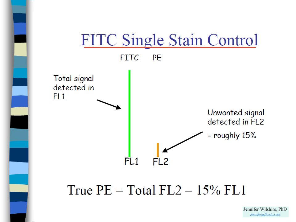
Kompenzace fluorescenčního signálu při vícebarevné detekci
Proces při kterém dochází k eliminaci všech fluorescenčních signálů kromě signálu z fluorochromu který má být na příslušném detektoru detekován Nastavení pomocí mixu mikročástic či buněk označených/neoznačených příslušnými fluorochromy. K. Souček Bi9393 Analytická cytometrie

124
Co je problém při vícebarevné detekci?
K. Souček Bi9393 Analytická cytometrie

125
Kompenzace fluorescenčního signálu při vícebarevné detekci
K. Souček Bi9393 Analytická cytometrie

126
“Bright” = good resolution sensitivity

127
Various fluorochromes-stain index

128
Choices for 6,- 8,- 10,- and more colors

129
Fluorochrome selection considerations

130
FITC Spillover Relative Intensity Wavelength (nm) 650nm 700nm 500nm
PerCP-Cy5.5 695/40 500nm 600nm FITC 530/30 Relative Intensity Wavelength (nm) 550nm PE 585/42 750nm 800nm
 550nm. PE. 585/ nm. 800nm.")
131
FITC Compensation Relative Intensity Wavelength (nm) 650nm 700nm 500nm
PerCP-Cy5.5 695/40 500nm 600nm FITC 530/30 Relative Intensity Wavelength (nm) 550nm PE 585/42
 550nm. PE. 585/42.")
132
FITC Compensation Relative Intensity Wavelength (nm) 650nm 700nm 500nm
PerCP-Cy5.5 695/40 500nm 600nm FITC 530/30 Relative Intensity Wavelength (nm) 550nm PE 585/42
 550nm. PE. 585/42.")
133
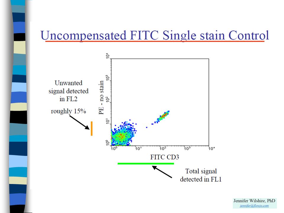
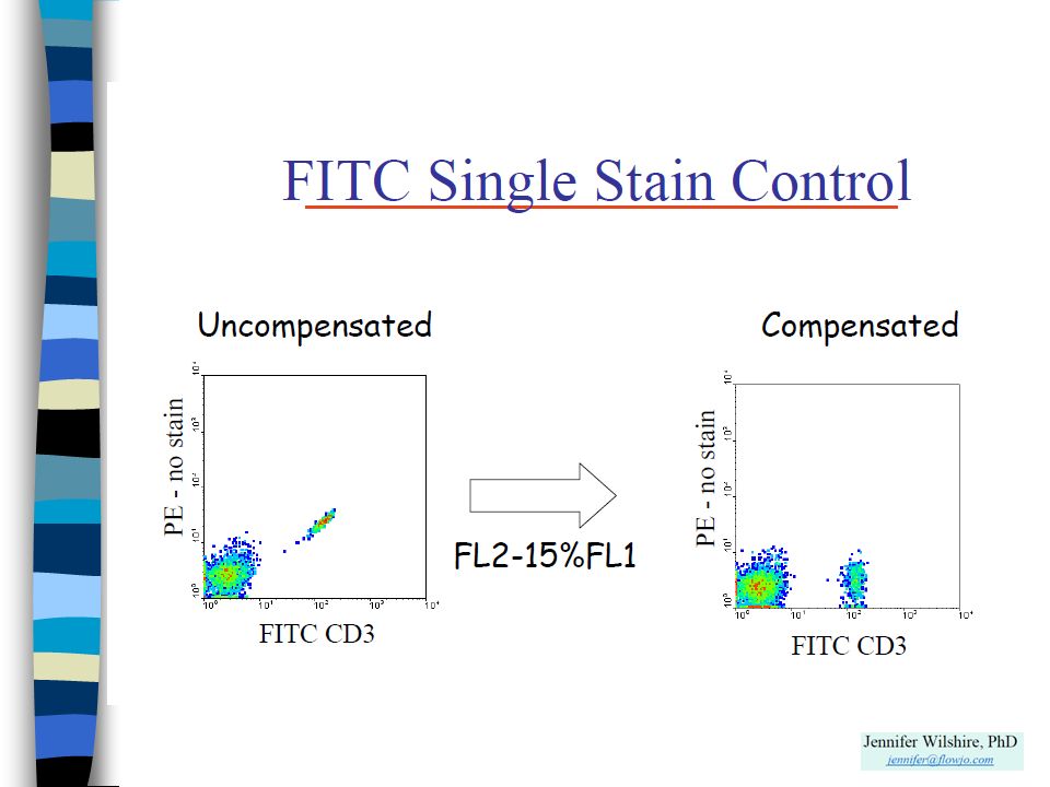
FITC Compensation Dot plot showing uncompensated FITC data
Dot plot showing compensated FITC data Biexponential dot plot showing compensated FITC data

134
FITC Spillover Relative Intensity Wavelength (nm) 600nm 500nm 550nm
530/30 Relative Intensity Wavelength (nm) PE 585/42
 PE. 585/42.")
138
Kompenzace fluorescenčního signálu
FITC positive & negative PE negative beads #2 K. Souček Bi9393 Analytická cytometrie

139
Kompenzace fluorescenčního signálu
FITC positive & negative PE negative beads NONE! K. Souček Bi9393 Analytická cytometrie

140
Kompenzace fluorescenčního signálu

141
Nastavení kompenzací značené mikročástice – pro běžně konjugované fluorochromy značené buňky – pro vitální značení parametr - detektor amp. FL FL kompenzace FL %FL2 FL %FL1

142
Effects of Changing PMT Values
FITC Voltage Increased by 5 V FITC Voltage Decreased by 5 V Correct Compensation

143
Which marker for compensation?
Small errors in compensation of a dim control (A) can result in large compensation errors with bright reagents (B & C). Use bright markers to setup proper compensation.
 can result in large compensation errors with bright reagents (B & C). Use bright markers to setup proper compensation.")
144
BD Comp Beads Always positive Bright staining
Save sample (HIV patients) Use the same antibody for compensation and the real experiment
 Use the same antibody for compensation and the real experiment.")
145
BD Comp Beads

146
Fluorescence Minus One
PBMC were stained as shown in a 3-color experiment. Compensation was properly set for all spillovers Courtesy Mario Roederer

147
Tandemové značky

148
Tandemové značky - příklad

149
Time Sample Left in Light
Tandems are light sensitive 0 hours 2 hours 22.5 hours PE (FL2) CD8 CD3 PE-Cy5 PE-Cy7 Time Sample Left in Light
 CD8. CD3. PE-Cy5. PE-Cy7. Time Sample Left in Light.")
150
Kompenzace - literatura
Mario Roederer - Compensation in Flow Cytometry Current Protocols in Cytometry (2002) John Wiley & Sons, Inc. M. Loken, D. R. Parks, & L. A. Herzenberg (1977). Two-color immunofluorescence using a fluorescence-activated cell sorter. J. Histochem. Cytochem. 25: M. Roederer & R. F. Murphy (1986). Cell-by-cell autofluorescence correction for low signal-to-noise systems: application to EGF endocytosis by 3T3 fibroblasts. Cytometry 7: S. Alberti, D. R. Parks, & L. A. Herzenberg (1987). A single laser method for subtraction of cell autofluorescence in flow cytometry. Cytometry 8: C. B. Bagwell & E. G. Adams (1993). Fluorescence spectral overlap compensation for any number of flow cytometry parameters. in: Annals of the New York Academy of Sciences, 677: K. Souček Bi9393 Analytická cytometrie
 John Wiley & Sons, Inc. M. Loken, D. R. Parks, & L. A. Herzenberg (1977). Two-color immunofluorescence using a fluorescence-activated cell sorter. J. Histochem. Cytochem. 25: M. Roederer & R. F. Murphy (1986). Cell-by-cell autofluorescence correction for low signal-to-noise systems: application to EGF endocytosis by 3T3 fibroblasts. Cytometry 7: S. Alberti, D. R. Parks, & L. A. Herzenberg (1987). A single laser method for subtraction of cell autofluorescence in flow cytometry. Cytometry 8: C. B. Bagwell & E. G. Adams (1993). Fluorescence spectral overlap compensation for any number of flow cytometry parameters. in: Annals of the New York Academy of Sciences, 677: K. Souček Bi9393 Analytická cytometrie.")
151
No Data Analysis Technique Can Make Good Data Out of Bad Data!
Shapiro’s 7th Law of Flow Cytometry

152
Shrnutí přednášky sorting zpracování signálu
vizualizace dat a „gating“ kompenzace Na konci dnešní přednášky byste měli: Znát základní principu sortování, popsat způsob zpracování signálu, rozumět lin / log zesílení signálu, rozeznat jednotlivé způsoby vizualizace dat, chápat základní principy „gatingu“, znát princip kompenzace signálu při vícebarevné detekci. K. Souček Bi9393 Analytická cytometrie

Podobné prezentace


, Ω(n 2 ), Θ(n·log 2 (n)), … Různé algoritmy mají různou složitost: O(n), Ω(n 2 ), Θ(n·log.>")


